Audible Sound
There is little difference between detecting ultrasound and audible sound as far as the concept is concerned. (Caron, James N., et al. Review of scientific instruments 69.8 (1998): 2912-2917.) Changes in the air's index of refraction caused by the sound waves deflect the beam of the light from its original path. To maximize sensitivity, a different photodetector is used, and we have developed some simple amplifiers.
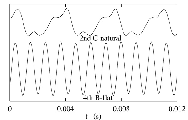
The technique has been used to record such acoustic waveforms as clapping, the human voice at normal, and musical instruments. Shown in the figure below is a sound wave produced by a bassoon, played by the inventor. Soon this site will have a link to a recorded message first played at an Acoustical Society of America meeting.
Fig 2: Several notes played on a bassoon and recorded by GCLAD
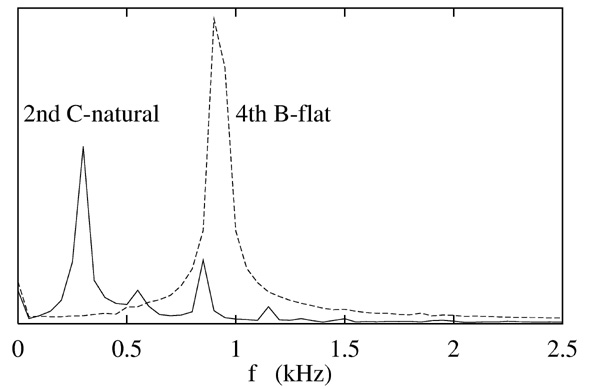
Fig 3: Fourier transform of the tones. As evident in the sound wave, the low C-natural contains several overtones.
Underwater Detection
In recent years, we have been studying the use of this technique in a water environment. (Caron, James N., and Pratima Kunapareddy, AIP Conference Proceedings. Vol. 1581. No. 1. American Institute of Physics, 2014.) Instead of 'gas-coupled', the acoustic wave is coupled to the laser beam with water. This has advantages with sensitvity, especially with freqeuncies higher than 500 kHz. It also allows the ulstround to be detected at different positions. We built a C-scanning system, depicted in the diagram, that passes the beam through the water twice. This provided three strong signals, a direct wave from the transducer to the beam, a reflected wave from the sample surface, and a transmiited wave.
Fig4: An underwater GCLAD setup used for sensing ultrasound in materials. An X-Y scanner moves the material in front of the detection point.
The C-scans below were built up by recording a single trigger event at each position for the X-Y scanner. The amplitudes of each wave crossing were recorded as a function of position, making the C-scans. The material in this case was a polymer-carbon fiber composite.
Fig 5: Images from the C-scanning of a composite plate. The first is an optical image. The next three result from measuring the amplitude of the ultrasound wave as it crosses the laser beam.
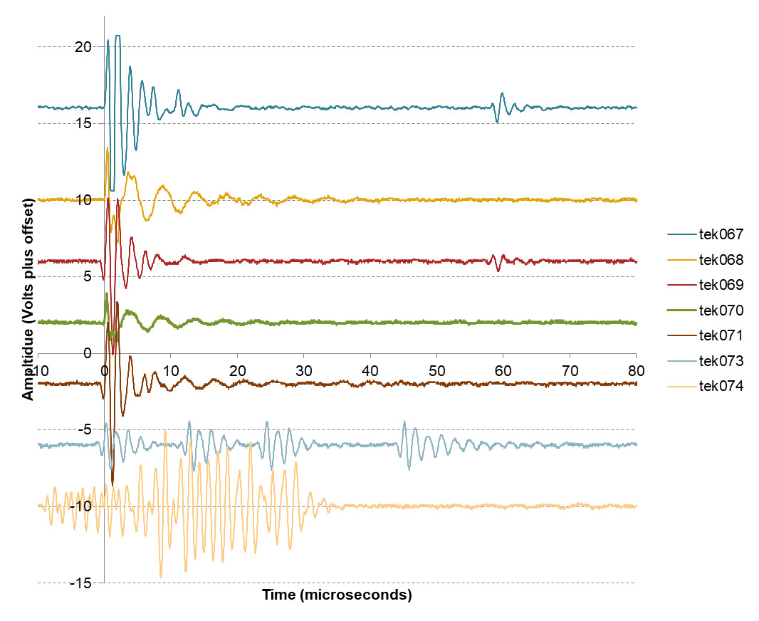
Lately we have been investigating the sensing of ultrasound in super-heated fluids. To meet this goal, we directed a laser beam through a beaker of tap water that was heated to boiling from below. The graph below shows the ultrasound waves recorded from different types of events.
Fig 6: Ultrasound waveforms recorded in a boiling beaker by optical beam diversion (also called Liquid-coupled laser acoustic detection).


